Ok so I'm being thick as shit here
Please someone tell me the setting I require to be able to get readings on my car


Ok so I'm being thick as shit here
Please someone tell me the setting I require to be able to get readings on my car


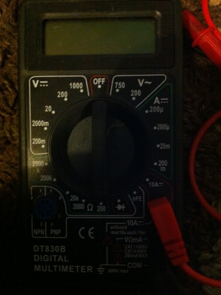
What you want to measures


From off position rotate left to 20..
Thats 20v dc .. all car circuits are 12v dc so this will read all... except ht leads which u should mpt mess with as they pack a wallop pf around 70k volts and will make yer hair stand up like Einsteins hair..
Lol right that's well remembered then :(
Cheers az


Not that it helps, but I like it. :-)


With the probe leads in the current position you will only be able to use the Amps draw setting, for all other functions like voltage and resistance checks you need to have the red probe plugged into the next port down ....
VΩmA
Ok cheers paul


continuity
Do this check with power off generally.
continuity is a regular used check on auto circuit. if you want to check if a wire is broken (severed) melted etc. turn the dial to Ohms (resistance) the omega symbol looks like an upside down U, 200 ohms is good, and look at the display on the readout.. it should display this : ------- this means no resistance.
now touch the probes together you should get a tiny value on the display , something like 0.01 or 0.1 or even 0.00 that means there is a measurable resistance. therefore the circuit is continuous.
to test wires in your car are broken or not;
put a tester on exposed wire either end of the section of wire you want to check.. if you get a resistance value , basically anything bigger than ------- !! any number displayed means the wire has not broken completely.. (because it has a measurable resistance)
wire with a break will display like this : -------- .
you can also test most auto fuses in the same manner, fuses have two metal bits sticking out the top, throw the probes across them with the meter set on resistance ... and you should see a resistance value. if all you see is ------- then the fuse is open circuit/blown (fubarred!) . then double check your work by touching the meter probes to check the probes are correctly connected to meter. (you would see a value like 0.1 / 0.01 or even 0.00 ! pop up again) it just means your probes are connected correctly to meter because you are getting a reading, its a gaurantee.
you can use a resistance check in many ways, to find the routing of wires in bundles. in looms especially. just probe the wire you want to check one end, and then go through the other wires in order until you find one with resistance, thats more than likely your wire. sometimes other wires also have continuity in bundles, it bcomes confusing then, so its a good time to check colours match also.
most modern meters have an audible beep for continuity, makes it a whole lot easier instead of trying to look at screens for values and to hold probes. comes with experience i guess, i have two meters the one that beeps gets used a whole lot more.
checking 12v
whenever checking the 12v dc circuit on car, put the black probe on something like a door catch bolt or a clean bolt head (any exposed clean metal part bolted to the chasis which is not insulated from negative ground). rust is not good enough contact, neither is a dirty contact . you can scratch a bit with the tip of the probe they are usually sharp. or if your unsure, sand the bastid with some sandpaper to ensure metal tip contact. if your close enough to the battery just crack the black on the battery -ve .
if measuring current; it has to be in series, i.e, in Line to the wire. one probe on one bit of wire, the other probe on the same wire a little further down, but with the test probe plug into the top plug '10A' instead of the middle plug. as paul said the top hole is for larger current measurement only from 200ma-10a maximum . take a reading, maximum reading time 10s, because its not fused. the smaller current range upto 200 milliamps is fused and read using the middle hole for red plug and to use other 'A' selectable readouts.. 20ma etc, 200.
hth.
btw any electrical people want to correct anything go ahead, i am mechanical.
the 200+750 is for domestic or 3ph testing, would avoid testing at home completely. stick to the 20vdc range
Last edited by adamh; 06-08-2013 at 20:03.
......in the bluecorner , fighting out of japan....


Really good thread and very useful to us Bodger types who don't get to do things like this very often.
Would one of you lovely admins sticky this, please.
“Where I'm going is not nearly as important as what I'm driving to get there.” ― Jay Leno
I've moved it out of "off topic" and into "electrical" and stuck it :thumbsup:
 Posting Permissions

 Reply With Quote