Hi Paul,
I am using existing replays form the doner car, Is this OK?


Hi Paul,
I am using existing replays form the doner car, Is this OK?


Yes that's fine, the original relays are better if anything.
When you have 3 relays working we can make a start.
Hi,
I am abit confused, the relays from donner has numbers 3,4, 2 ,1 which is different to what the 87,30,55,56 you mentioned. What does these numbers represent?
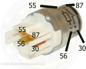
If you look on the side of the relay it shows a diagram of its pins , the ones on the switched input/output ---/ --- are the same as 87 and 30
Here is a quick diagram showing the pins numbered as a normal 87/30 relay....
Last edited by Paul Woods; 30-04-2012 at 07:24.


Here's one for ya. Why do they get numbered with the numbers they do? Why not 1,2,3,4?
You know what, i honestly don't know why, they've just always been called that.


It's because the numbering is based on the original Latin counting system.Originally Posted by Paul Woods

Chris.
Hi, thanks, got that now. Had to figure out a spot to fit the unit, now ready to add final wires. Should be ready to go in the evening
Hi Paul,
3 relays fitted and seems to be working fine..... Ready for the next step in the wiring......?
Good news, so all 3 relays have an output when you switch the ignition on, ok. I've done this diagram for you, it shows the N1 connector and some wiring colours, now these colours changed over the years so don't treat them as gospel, but most should be correct. The wiring positions are correct though, this diagram is numbered as if you are looking at the wires as they go into the back of the N1 connector from the engine side.
First job is to wire your three relay output wires to terminals 1 (White/Blue), 7 (Black) and 12 (Black/Red), obviously one relay per wire.
Make sure you fully identify those wire locations, some N1 connectors are numbered from the chassis side of the plug.
Run battery permanent supply to pin 11 (White/red)
Run an ignition feed (from one of your relays) to pin 6 (Black/Yellow) - for alternator.
You will need clocks installed or at least a bulb on the dash to get the alternator working, i'll wait until you have done the above and reported back.
 Posting Permissions

 Reply With Quote