***This is just a guide, check all your wires before connecting yourself etc....***
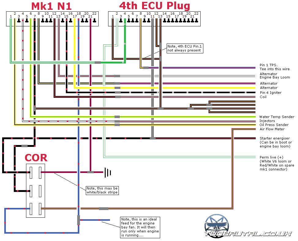
This is to supplement the existing write ups and various threads, here is the wiring on my 1986 mk1a so far.
Available as a bitmap with better colours here


***This is just a guide, check all your wires before connecting yourself etc....***
This is to supplement the existing write ups and various threads, here is the wiring on my 1986 mk1a so far.
Available as a bitmap with better colours here
Last edited by black_mk1; 15-06-2008 at 18:32. Reason: Updated to include alternator wiring as per below posts
My build thread -> Clicky
My Build progress -> |-----------------------------------------|


I think you'll need to hook up the other alternator wires like I had to yesterday.
:)Originally Posted by Paul Woods
Priorities change, passions do not.
Hmm interesting, will check tomorrow and update diagram if necessary.
I have a couple of other bugs to sort out, lack of dash warning lights etc.
My build thread -> Clicky
My Build progress -> |-----------------------------------------|
Those two wires will give you the battery and charge lights when you go to the ignition stage before starting the engine :)
Priorities change, passions do not.
ok, updated cheers :)
My build thread -> Clicky
My Build progress -> |-----------------------------------------|

Outstanding work.Sticky-ing the thread now :thumbsup:
If it's not quite finished yet could you stick a bid red label at the top to say work in progress or something similar? I'd hate to see a newbie blindly copying it and then blaming you if he had a problem!
Cheers,
Owen.
----MY Manual SC------Lyn's Auto SC ---- NA/SC MK1.5 Donors-----
"What have you angle ground today?" :twisted:
TB BIG Affiliate - SWAT Motorsport Forum Link Picture Album Shop Link
Good point, done :)
I'll wait for the "Paul Woods seal of approval" :thumbsup:
My build thread -> Clicky
My Build progress -> |-----------------------------------------|


theres a problem with that diagram on the check engine light,pin 4 on the 4th ecu plug is for CEL (usually green) and that should go to pin 1 on the N1..... in the diagram you have pin 1 on the N1 going to pin 9 on the 4th ecu plug which is wrong.
Also it might be worth adding pin 1 on the 4th ecu plug joined onto pins 12 and 13 as this is 95% the case with v6 ecu's,yours is the rare exception that we have only found once so far with no pin 1.
Other than that its a great diagram :thumbsup:
Jeez Paul, what did that take you? 30 seconds to diagnose a complete V6 wiring diagram? We are not worthy...
Owen.
----MY Manual SC------Lyn's Auto SC ---- NA/SC MK1.5 Donors-----
"What have you angle ground today?" :twisted:
TB BIG Affiliate - SWAT Motorsport Forum Link Picture Album Shop Link
Added you as number 11 to the swap register. Bloody well done mate!
Owen.
----MY Manual SC------Lyn's Auto SC ---- NA/SC MK1.5 Donors-----
"What have you angle ground today?" :twisted:
TB BIG Affiliate - SWAT Motorsport Forum Link Picture Album Shop Link

 Reply With Quote